3D Printing
A couple of months ago something broke in my office. Typically in a modern office, especially at a software development company, when something breaks it is software with bugs. For a change it turned out to be a hardware failure, and not hardware like an SSD or their Air Con (which happens to frequently break) but a gear inside a large piece of archaic office machinery.
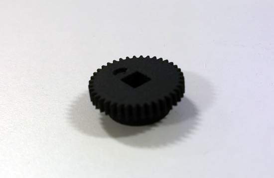
After dismantling the original mechanism we noticed one of 4 main gears had some teeth missing. After a fruitless search online for a replacement gear and finding it would cost an exorbitant amount to get a replacement from the manufacturer we thought we might give the new fad of 3D Printing a go instead of scrapping the whole machine.
The task of getting the broken gear turned into CAD fell to me as I have some basic CAD experience from helping friends at university who did engineering courses. As a software developer you often get roped in to doing all sorts of hardware and software work. Friends and family assume anyone who works as a software developer MUST know everything computer related from how to change a ring tone on an iPhone to using CAD to copy a stapler in first year of university using software you’ve never even heard of. Thankfully for me the last example is all too true and actually made me learn something useful!
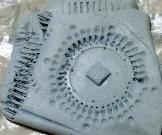
Step one was to measure the original gear. I have no tools or accurate callipers so everything was done with pencil drawings, reasoning and a basic ruler the same as you’d find in pencil cases across the globe. I also used Blu-tac as shown above to make an impression of the gear. This made counting teeth easy (as can be seen by the indents in/around the teeth made by me counting) as well as finding the tooth-spacing by rolling it in the Blu-tac and measuring the distance between marks.
Once I knew the rough dimensions I found an excellent piece of software called Gear Template Generator which helped me double check my measurements made sense as well as letting me export a DXF of the gear outline.
Once I created what I thought looked like a reasonably accurate representation of the gear and exported it as a DXF which could be imported into PTC Creo Elements/Direct Modeling Express. I chose Creo as during my first year of university I helped someone model a stapler using software called Pro-Engineer, which has since been renamed Creo, and found it wasn’t too bad to work with. The DXF file just gave me the outline of the gear, using this I could extrude up, mark the centre, make a circle in Creo and extrude that up to make the mode of the gear. Using the centre mark I could also add a square cut-out for the shaft. This was pretty much all the gear needed in terms of modelling.
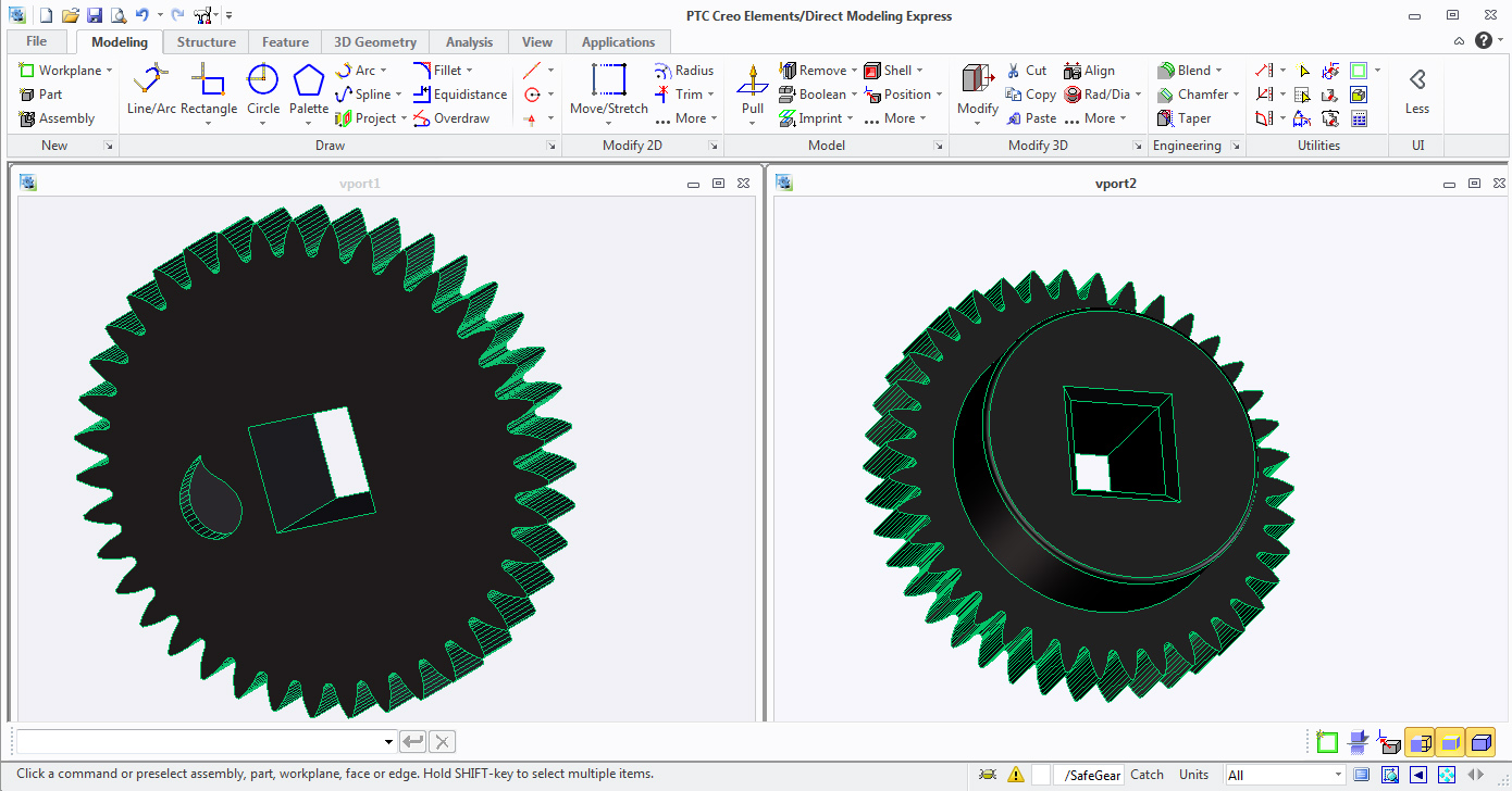
Once the model was created and had roughly the dimensions I was expecting I decided to be fancy and add a rounded edge to the circle surrounding the shaft hole and a chamfered edge to the shaft hole hopefully making seating of it easier when we got it. I also took the Fivium droplet logo from Illustrator and exported it as a DXF too. I could then import that into Creo on the workplane for the gear face and use it as a cut-out to imprint the company logo into it.
Once the gear was fully modelled and I was roughly happy with the dimensions I headed straight for Shapeways. I’d heard of their company a few times and been itching for a legitimate excuse to get something printed with them. Thankfully the process was as simple as exporting an STL file, uploading it to Shapeways and waiting for them to analyse the file and letting me know that the teeth might not be great due to the accuracy of the printing process. I ignored these warnings, grabbed a company credit card, and headed for the Shapeways checkout screen to have the gear printed in hard black plastic.
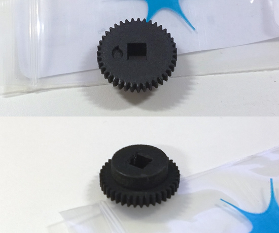
A couple of weeks later it arrived and it looked great!
The plastic was nice and hard, the teeth seemed to be the right spacing when hand-rolled against the engaging gear and the Fivium droplet showed up nicely despite only being in-set a couple of mm. We had to file the inside of the shaft-hole to make it fit but that was probably due to me measuring with a simple ruler rather than proper callipers.
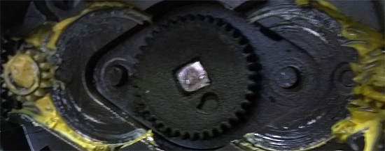
Once seated fully in the mechanism it all seemed great.
Unfortunately not every first attempt at something ends in full success, and this was one of those times. Due to a combination of taking measurements with a ruler and 3D printing not currently able to print fine details, such as the thin ends to gear teeth, my gear was slipping instead of fully engaging the two gears positioned either side of it.
Next time I think I’ll go for proper measuring tools and possibly model and print more than just the one gear. That was I can model the whole mechanism and check everything will mesh rather than mixing existing parts of unknown size with my badly measured parts!
If you have a broken piece of mechanical hardware in your home or office I’d definitely suggested having a go at 3D printing your own replacement parts. Even if my first attempt wasn’t 100% success the process was fun and I learned a few new things about 3D modelling/CAD. As a software developer it was also a nice change to do something on a computer that resulted in a tangible product I could touch and watch move, definitely made a change from the land of 2D and text which I usually inhabit.